Introduction
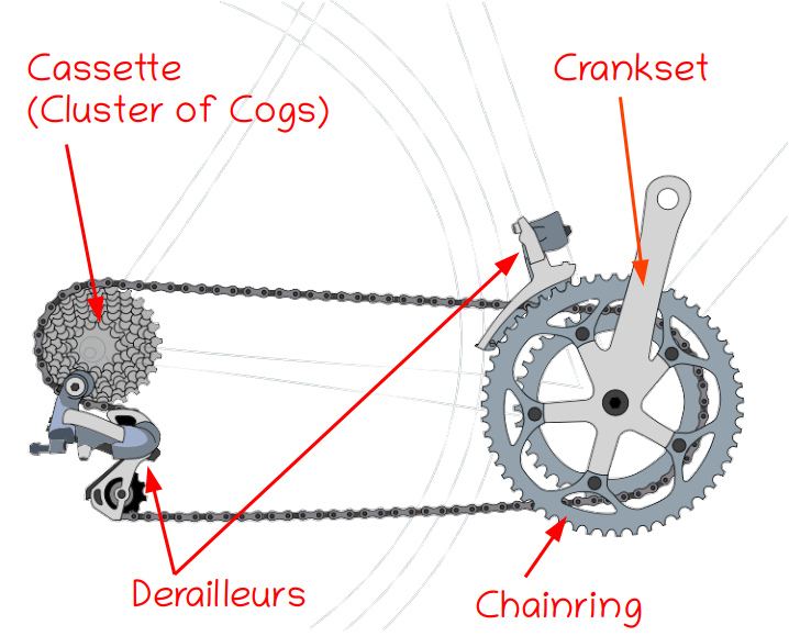
A bicycle converts the motion of pedaling into rotation of one of the wheels, which drives the bike forwards. How much the drive wheel rotates for each turn of the pedals depends on the gearing of the bike. Some bikes are single-speed, which means that the relationship between how much the wheels turn compared to how much the pedals turn is fixed and cannot be changed while riding. Other bikes have selectable gears, usually through a system of cogs and chainrings, where derailleurs shift the chain from one cog to another to change the gearing of the bicycle on the fly. Sometimes gear changes are accomplished through hub gears or some other less common system, but no matter how the drivetrain works, the bike will be slower but easier to pedal when in a low gear and faster but harder to pedal in a high gear.
Original Image: Derailleur Bicycle Drivetrain by Keithonearth, licensed under a
Creative Commons Attribution-ShareAlike 3.0 Unported license.
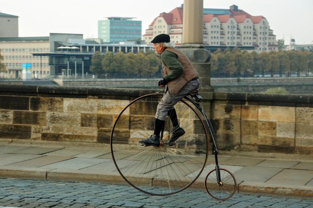
Before diving deeper into the world of geared bikes let’s understand some fundamental concepts by taking a look at the Penny-Farthing, the first type of bicycle ever invented. The Penny-Farthing is a direct drive bicycle, which means that the crank arms are directly connected to the wheel hub. There are no gears to multiply the force applied to the pedals, so one turn of the pedals corresponds to exactly one rotation of the drive wheel. This means that the gearing of a Penny-Farthing is only determined by the size of the front wheel, which is what gives the bike its distinctive high-wheel design. This also makes it really easy to visually understand how a Penny-Farthing is geared: the larger the front wheel, the higher the gearing and therefore the faster the bike.
Pennyfarthing in Dresden by Fjmustak, licensed under a
Creative Commons Attribution-ShareAlike 4.0 International license.
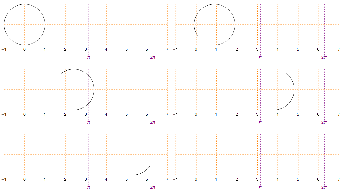
So how can we quantify the gearing of a Penny-Farthing exactly? One way would be to figure out how far the bike travels foward for each turn of the pedals. This is really easy: since one turn of the pedals causes exactly one rotation of the main wheel, the distance the bike travels forwards per pedal stroke is exactly qual to the circumference of the wheel.
Unfolding circle demonstration of pi by Jack Crawford, Public Domain Image
If a Penny-Farthing wheel is measured in meters, this quantity is known as the bicycle’s ‘meters of development’. For example, if the circumference of the wheel is 4.5 meters, the bike has 4.5 meters of development, which means that one complete turn of the crankset causes the bike to develop, or travel forward 4.5 meters. But in the world of imperial measurements, people decided that it made more sense to compare the diameter rather than the circumference of different drive wheels, which is where the concept of gear inches comes into play. Gear inches is the most common way of quantifying bicycle gearing in English, and for a Penny-Farthing the gear inches of the bicycle is simply equal to the diameter of its main wheel. A Penny-Farthing with a main wheel that is 60 inches in diameter has 60 gear inches, and will be faster than one with a 54 inch diameter wheel which would only have 54 gear inches. Gear inches can easily be converted to meters of development using the following equation:
\text{Meters of Development} = \text{Gear Inches}*\Pi*(0.025\text{ Meters / Inch})As we know from geometry, the circumference of a circle is equal to its diameter * π (3.14159), so all this formula is doing is converting a diameter to a circumference and then converting inches to meters. In theory we could play around with this formula even more to calculate inches of development or gear meters!
Gear Ratios
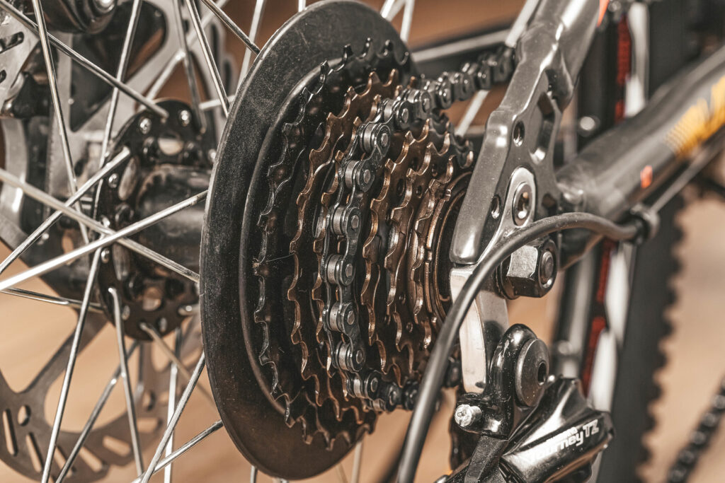
If a bike has gears, even if it’s a fixed-gear bike, one turn of the cranks doesn’t necessarily equate to one turn of the wheel anymore, which means that the distance the bike travels for each pedal stroke is not always equal to the circumference of the drive wheel – it varies depending on the selected gear combination. This logically implies that the gear inches are also no longer equal to the diameter of the drive wheel, but the calculation of gear inches still depends on the wheel diameter – the measured diameter just has to be modified depending on the current gear ratio of the drivetrain.
Bicycle gears cassette and chain on bike, close up by Marco Verch Professional Photographer on Flickr,
licensed under a Creative Commons Attribution Generic 2.0 license.
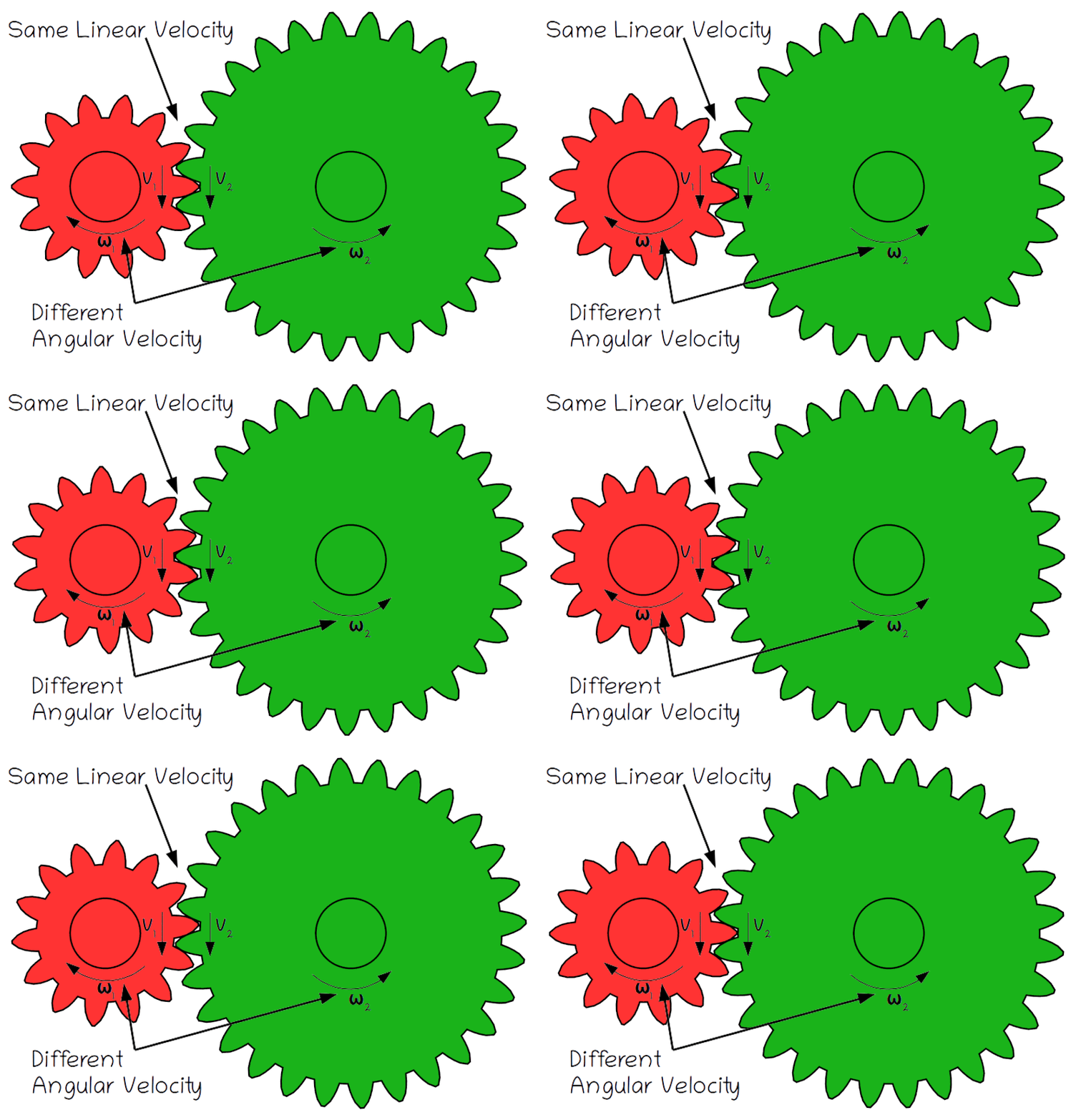
Every cyclist knows that when you’re in a higher gear it’s harder to pedal but you can go faster. This makes intuitive sense, but how does this work mathematically? Whether a set of gears meshes directly, as shown at right, or is connected via a chain, as in a bicycle, the fundamental property of a gear train is that the linear velocity (v, in meters/second) of two linked gears is the same. This means that the edges of each gear are moving at the same speed, because their rotation is locked together.
Original Image: Animated two spur gears 1 2 by Jahobr, Public Domain Image
What’s not the same though is the angular velocity (ω, in radians/second), or rotational speed of each gear. Angular velocity is defined as the amount of rotation (θ, in radians) per time (t, in seconds):
\omega=\frac{\theta}{t}The angular velocity of each gear is related to its linear velocity through its radius (r, in meters) like this:
v = r*\omega
The condition that the linear velocity of gears which mesh or are connected via a chain must be the same means that we can set the velocity of two gears equal to each other. That gives us the following relationship:
v_1=v_2
Therefore:
r_1*\omega_1=r_2*\omega_2
Which we can rearrange to give us two equal ratios:
\frac{\omega_2}{\omega_1}=\frac{r_1}{r_2}The number of teeth on a gear is proportional to its radius, which means that we can also write the equation like this (where N denotes the number of teeth on each gear):
\frac{\omega_2}{\omega_1}=\frac{N_1}{N_2}This ratio is called the gear ratio of a gear train, which is defined as the ratio of the angular velocity of the output gear to the angular velocity of the input gear:
\text{Gear Ratio}=\frac{\omega_2}{\omega_1}=\frac{r_1}{r_2}=\frac{N_1}{N_2}In the case of a bicycle, it’s easiest calculate the gear ratio by counting the number of teeth on the chainring and dividing this by the number of teeth on the cassette cog:
\text{Gear Ratio}=\frac{N_1}{N_2}=\frac{\text{Number of Teeth on Chainring}}{\text{Number of Teeth on Cassette Cog}}Gear ratios basically tell us how much faster or slower the cassette rotates compared to the chainring, for example if the chainring has 40 teeth and the cog on the casette has 20 teeth, the gear ratio would be:
\text{Gear Ratio}=\frac{N_1}{N_2}=\frac{40}{20}=2This would normally be written as a 2:1 gear ratio which means the with such a gear combination the cassete would be spinning twice as fast as the chainring, regardless of the cyclist’s cadence*. Since the crankset is fixed to the chainring and the drive wheel is fixed to the cassette (at least if you are pedaling forwards), this also implies that the drive wheel is spinning twice as fast as the crankset.
The formula implies that as the number of teeth on the chainring increases or the number of teeth on the cassette decreases, the gear ratio of the bike increases. This makes sense because it corresponds to our real-world experience: we can select a higher gear by either shifting the front derailleur to a bigger chainring or the rear derailleur to a smaller cog, and both options make the bike go faster at the expense of increased effort.
*Something which really confused me here while I was researching this article is that bicycle gear ratios are not specified the same way as other transmission gear ratios. In most applications, a 2:1 gear ratio means that the input gear spins twice as fast as the output gear, but in the cycling world it means that the output gear is spinning twice as fast as the input gear. This is why the equations given here and by other bicycle specific sources are usually the inverse of those found on generalized mechanical engineering or automotive websites.
Mechanical Advantage & Torque
The law of conservation of energy states that the power output at the drive wheel is equal to the power a cyclist imparts to the drivetrain, assuming there are no losses due to friction. This is true regardless of how the bicycle is geared: as long as the cyclist’s cadence doesn’t change, the amount of energy transferred (work) and rate of energy transfer (power) are the same in any gear. A set of gears takes advantage of this by trading speed for ease of turning to create a mechanical advantage.
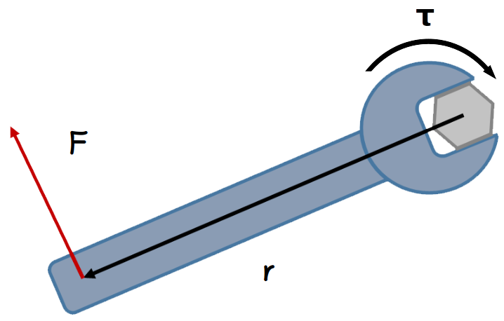
Mechanical advantage is defined as how much a machine multiplies the applied force between the input and the output. In the case of a set of gears, this is usually discussed in terms of torque, or rotational force. Torque (τ, in Newton-meters) is related to linear force (F, in Newtons) by how far away from the center of rotation the linear force is applied, which is the radius (r, in meters) of the gear:
Original Image: Kraftmoment by Andreas Tjernshaugen, licensed under a
Creative Commons Attribution-ShareAlike 3.0 Norway license.
\tau=F*r
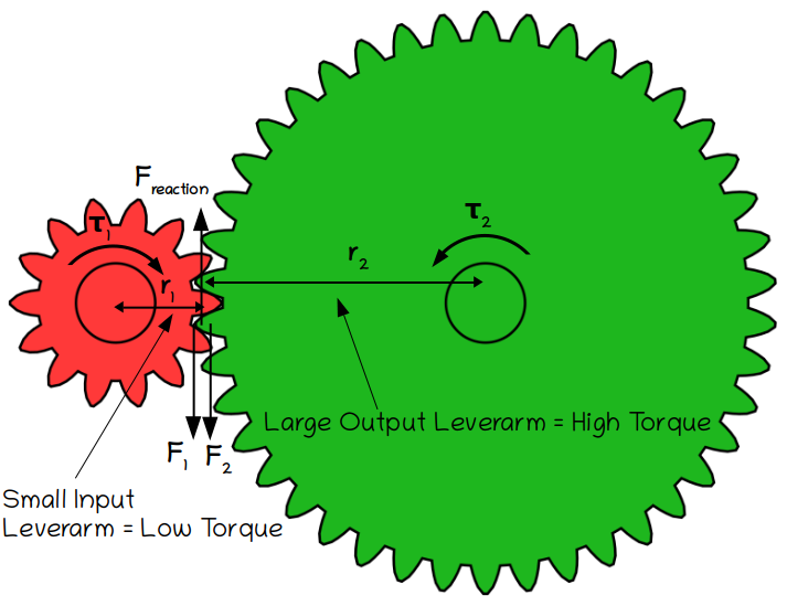
There are different ways of calculating the torque transfered through a gear train, but one way uses Newton’s 3rd Law of Motion, which states that every action has an equal and opposite reaction. This implies that the forces on the teeth of both gears at the contact point between two meshing gears (or two gears connected by a chain) must be equal.
Original Image: Animated two spur gears 1 2 by Jahobr, Public Domain Image
The mechanical advantage of a gearset is equal to its torque ratio. In order to calculate this we first rearrange the basic torque equation to get:
F=\frac{\tau}{r}Then we set the forces in each gear at the contact point between the gears equal to each other:
F_1=F_2
And if we plug in the equation for torque, we get:
\frac{\tau_1}{r_1}=\frac{\tau_2}{r_2}Which results in the following relationship:
\frac{r_1}{r_2}=\frac{\tau_1}{\tau_2}
But we already know from earlier that r1 /r2 is equal to the gear ratio, therefore:
\text{Gear Ratio}=\frac{r_1}{r_2}=\frac{\tau_1}{\tau_2}The important conclusion here is that the gear ratio has the opposite effect on torque than it does on angular velocity. As the gear ratio increases, the rotation of the cassette becomes faster compared to the rotation of the chainring, but the torque transmitted by the cassette becomes lower compared to that transmitted by the chainring:
\text{Gear Ratio}=\frac{\omega_2}{\omega_1}=\frac{\tau_1}{\tau_2}This explains what happens when you shift gears on a bicycle: in a lower gear, the output torque is higher than the input torque, which makes it easier to pedal. On the other hand, the output angular velocity is lower, which means that it’s harder to reach high speed.
Gear Ratio, Gear Inches and Meters of Development
The equations above show how we can use the number of teeth on the chainring and cassette to calculate a gear ratio, and how gear ratios can be used to calculate how the selected gear combination affects the rotational speed and torque at the cassette. But power isn’t transfered to the ground through the cassette, it’s transfered through the wheel, so how can we capture the effect of this mathematically? The obvious answer is to relate gear ratio to gear inches and meters of development.
Recall from the beginning of this article that a bicycle’s development is equal to how far it travels forward per rotation of the crankset. The gear ratio of the drivetrain tells us how fast the cassette rotates compared to how fast the crankset rotates, but since the crankset is fixed to the chainring and the drive wheel is fixed to the cassette (at least if you are pedaling forwards), this is equal to how fast the rear wheel is rotating compared to the crankset:
\text{Gear Ratio}=\frac{\omega_2}{\omega_1}=\frac{\omega_\text{wheel}}{\omega_\text{crankset}}Which can be rearranged to get:
\omega_\text{wheel}=\text{Gear Ratio}*\omega_\text{crankset}Now we plug in the definition of angular velocity (with θ in radians and t in seconds) to get:
\omega=\frac{\theta}{t}Therefore:
\frac{\theta_\text{wheel}}{t}=\text{Gear Ratio}*\frac{\theta_\text{crankset}}{t}Since the wheel and the crankset are living in the same universe, they both experience the same time, so we can cancel out t and rearrange the equation to derive:
\frac{\theta_\text{wheel}}{\theta_\text{crankset}}=\text{Gear Ratio}This equation shows us that the gear ratio is also equal to how much the wheel rotates compared to how much the crankset rotates. Now the goal is to convert this to a relationship between how far the bicycle travels compared to how much the crankset rotates. How far the bike travels is equal to the distance that the outside edge of the drive wheel travels around its axle. This can be calculated by plugging in the definition of a radian, which is the relationship between an arc length (s, in meters) and the radius of the arc (r, in meters):
\theta=\frac{s}{r}The arc length traced by a point at the edge of the wheel is equal to the distance the bike travels forward, therefore:
\theta_\text{wheel}=\frac{\text{Distance Travelled}}{r_\text{wheel}}And:
\frac{\frac{\text{Distance Travelled}}{r_\text{wheel}}}{\theta_\text{crankset}} = \text{Gear Ratio}Which can be rearranged to give:
\text{Distance Travelled}=\text{Gear Ratio}*\theta_{crankset}*r_\text{wheel}Now we can calculate meters of development by calculating the distance travelled based on one complete rotation of the crankset, which occurs after 2π radians-the definition of a circle. We can also plug in d=2*r to convert the radius of the rear wheel to its diameter:
\text{Meters of Development}=\text{Gear Ratio}*\pi*d \text{ (in meters)}This is the generalized equation for meters of development which applies to any kind of geared bike, as well as direct drive bikes, in which case the gear ratio is simply set to 1.
Now here’s where things get interesting again. The equation above is the equation for how far a bike travels after one rotation of the crankset, which is is only equal to one rotation of the drive wheel when the gear ratio is exactly equal to 1. This means that the gear inches of the bike is also equal to the diameter of the drive wheel only when the gear ratio is exactly 1. However, when the gear ratio is not equal to 1 we can still calculate an ‘equivalent’ wheel diameter which would in fact rotate exactly once for each turn of the cranks. The diameter of such a ‘virtual’ wheel would be equal to:
d_\text{equivalent}=\text{Gear Ratio}*dThis diameter would actually be the wheel diameter necessary to build a direct drive bike such as a Penny-Farthing with the same gearing as a geared bike with a certain gear ratio. For example, if we select a gear combination with a 4.5:1 gear ratio on a standard 28″ bicycle and wanted to make a Penny-Farthing with the same gearing we would have to give it a whopping 126-inch front wheel – that’s over 10 feet (3m)!
In any case, as long as we measure the diameter of the wheel in inches, this equation turns into the generalized equation for gear inches:
\text{Gear Inches}=\text{Gear Ratio}*d\text{ (in inches)}This means that to calculate gear inches for any bike, we simply need to measure its wheel diameter in inches and multiply the result by the current gear ratio.
Now that we have a basic understanding of gear ratios, gear inches and meters of development, let’s do an example. Suppose that a bike has 26″ wheels, the front chainring has 32 teeth, and the cassette cog has 20 teeth. How many gear inches does such a gear combination have, and how far does such a bike travel per rotation of the carnkset? First we calculate the gear ratio:
\text{Gear Ratio}=\frac{N_1}{N_2}=\frac{32}{20}=1.6Again, this means that the cassette is spinning 1.6 times as fast as the chainring. Next we use the wheel diameter to calculate gear inches:
\text{Gear Inches}=\text{Gear Ratio}*d = 1.6*26=41.6\text{ inches}This means that in order to build a Penny-Farthing with a gear ratio of 1.6:1, we would have to fit it with a main wheel that is 41.6 inches in diameter. Finally we can calculate meters of development:
\text{Meters of Development} = \text{Gear Inches}*\Pi*(0.025\text{ Meters / Inch})=41.6*3.14159*0.025=3.27\text{ meters}This means that such a bike would travel 3.27 meters forward for every turn of the cranks.
Internal Hub Gears
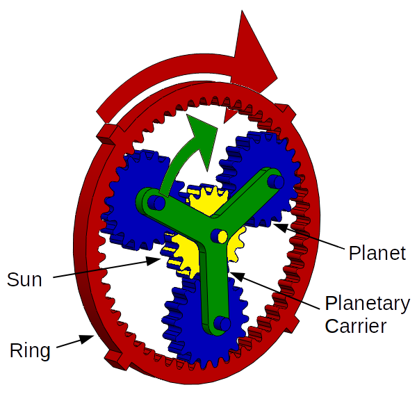
Gear inches and meters of development are easy to calculate for a bicycle with derailleurs, but what about for bikes which have internal gear hubs? Internal gear hubs use a special gear system called a planetary gearset, in which an inner sun gear is linked to an outer ring gear by several planet gears, which are held together by a planetary gear carrier. The advantage of a planetary gearset is that it takes up little space, and a single planetary system can also achieve multiple gear ratios depending on which component acts as the input and which acts as the output.
In a bicycle hub the sun gear is normally fixed in place, the planetary carrier is driven by the chain via the sprocket on the hub, and the ring acts as the output, which drives the wheel. The details of how planetary gears work is really beyond the scope of this article, but just for completeness the gear ratio of such a gear train is usually (although the exact arrangement of the gears can vary) given by:
Original Image: Bicycle hub gear by AndrewDressel on Wikimedia Commons,
licensed under a Creative Commons Attribution-ShareAlike 3.0 Unported license.
\text{Internal Hub Planetary Gear Ratio} = \frac{N_\text{ring}+N_\text{sun}}{N_\text{ring}}=1+\frac{N_\text{sun}}{N_\text{ring}}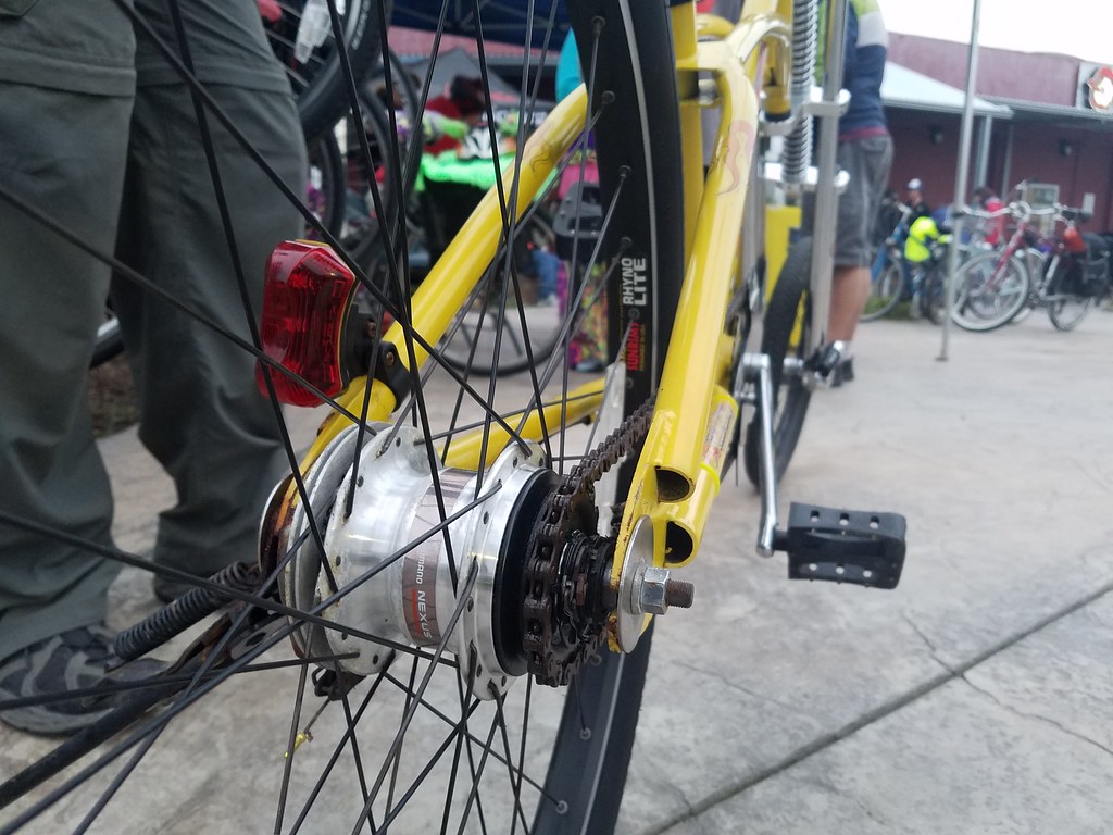
Of course it’s not very easy to count the number of teeth on the cogs of an internal gear hub because they are hidden by the hub’s housing, but luckily the manufacturers of these hubs typically publish a table of gear ratios for each gear, for example Shimano 7-speed hubs have the following gear ratios when a 20-tooth sprocket is used on the hub:
1st Gear = 0.63
2nd Gear = 0.74
3rd Gear = 0.84
4th Gear = 0.99
5th Gear = 1.15
6th Gear = 1.34
7th Gear = 1.55
$200 Shimano Nexus 7 speed hub on a 30 year old cruiser bicycle by Richard Masoner / Cyclelicious on Flickr,
licensed under a Creative Commons Attribution-ShareAlike 2.0 Generic license.
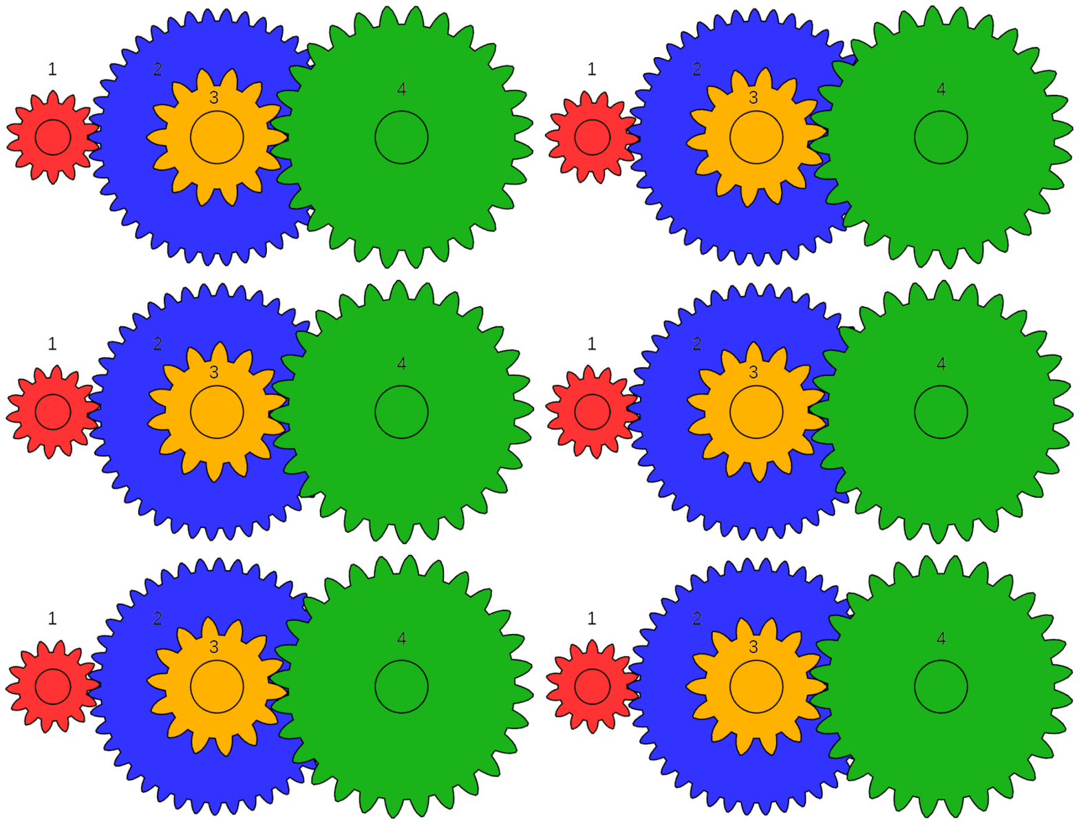
That’s not the whole story though because hub gear systems still use a chain to transfer power between the chainring and the sprocket, which affects the overall gear ratio of the system. This results in a compound gear, which is where the output gear of one set of gears is connected to the input gear of another via a shaft. This basically gives allows the overall ratio of the gear train to be split into two stages.
The yellow and blue gears in the animation at right are an example of a compound gear because they are rotating at the same speed. The overall arrangement of gears is similar to that on a bicycle except that on a bicycle the output of the compound gear is the input of a planetary gear. The red gear is analagous to the chainring, the blue gear to the sprocket on the hub, the yellow gear to the input gear on the internal gear hub, and the green gear to the output on the internal gear hub.
AnimatedGears by Jahobr, Public Domain Image
Calculating the overall gear ratio of a compound gear is done by multiplying the gear ratio of each stage together. This relationship can be derived in different ways but perhaps the simplest way is to analyze the kinematics of the gear train, which is the relationship between the motion of each component. In the gear train shown above the red gear drives the blue gear and the yellow gear drives the green gear. Let’s call them gears 1, 2, 3, and 4. The overall gear ratio of the system is defined as:
\text{Gear Ratio}_\text{overall}=\frac{\omega_4}{\omega_1}Even though gear 2 is connected to gear 3, gears 1 and 2 still behave as a normal two gear system according to the following equation:
\text{Gear Ratio}_\text{1,2}=\frac{\omega_2}{\omega_1}As do gears 3 and 4:
\text{Gear Ratio}_\text{3,4}=\frac{\omega_4}{\omega_3}The key observation is that gears 2 and 3 are fixed together, which means that they rotate at the same speed. This implies that their angular velocities are the same, which we can express mathematically with the following equation:
\omega_2=\omega_3
Therefore we can rewrite the relationship between gears 1 and 2 as follows:
\text{Gear Ratio}_\text{1,2}=\frac{\omega_3}{\omega_1}Now we want to find the relationship between the intermediate gear ratios and the overall gear ratio, which we can do by multiplying them together, because it allows us to cancel out ω3:
\frac{\omega_3}{\omega_1}*\frac{\omega_4}{\omega_3}=\frac{\omega_4}{\omega_1}This works because we can cancel out ω3. Now we can plug the definition of each intermediate gear ratio back into this equation to get:
\text{Gear Ratio}_\text{1,2}*\text{Gear Ratio}_\text{3,4}=\text{Gear Ratio}_\text{overall}This relationship works even if one of the gear stages is a planetary gear, such as in an internal hub gear.
In any case, it is important to note that the ratio of the number of teeth of gear 4 compared to gear 1 cannot be used to calculate the overall ratio of a compound system, but we can use the above equation to derive the relationship between the number of teeth of each gear and the overall gear ratio as follows:
\text{Gear Ratio}_\text{overall}=\text{Gear Ratio}_\text{1,2}*\text{Gear Ratio}_\text{3,4}=\frac{N_1}{N_2}*\frac{N_3}{N_4}The above equations can be extended to a gear train with any number of compound stages, and the overall gear ratio equation can also be plugged into the equation for gear inches to come up with a gear inches equation for internal hub gears:
\text{Gear Inches (Hub Gears)}=\text{Wheel Diameter in Inches}*\text{Gear Ratio of Chainring to Sprocket}*\text{Gear Ratio of Hub}This equation can even be generalized to any other type of bicycle drivetrain such as a shaft drive. No matter how the power is transmitted, gear inches can be calculated by multiplying the wheel diameter with the product of all of the intermediate gear ratios. And of course the exact same logic can also be applied to calculate meters of development for any situation.
Let’s finish off with another example. Suppose we have a bicycle with a 44-tooth front chainring, a Shimano Nexus 7-speed hub with a 20-tooth sprocket in 5th gear, and 28 inch wheels. How would we calculate the gear inches of the drivetrain?
First we have to go to the table of gear ratios for a Shimano Nexus-7 hub to find that the gear ratio in 5th gear is 1.15, and then we plug everything in as follows:
\text{Gear Inches}=d*\frac{N_1}{N_2}*\text{Hub Gear Ratio}=28*(44/20)*1.15=70.84\text{ Inches}Gear Inches in Practice
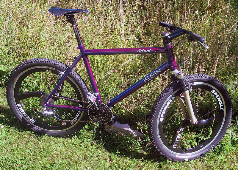
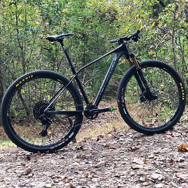
So now that we have an understanding of what gear inches means, what is this number actually good for? The main thing is that it gives us a way of comparing the drivetrain of different bicycles, which is easiest to do with one of the many online gear calculators which do the calculations for us (these calculators also account for the effect of different tire sizes on the diameter of the wheel). For example, let’s say that we want to compare a 26″ mountan bike from the early 2000s with a 22/32/42 tooth triple chainring, an 11-32t cassette and 1.5″ tires to a modern 1x 29er with a 32t chainring, a 10-51t cassette and 2.2″ tires. After plugging everything into the calculator we can see that the 26″ mountain bike has a range of 17.26 to 95.53 gear inches, while the 29er has a range of 18.20 to 92.44 gear inches.
Klein Adroit Burgundy Blue, 06 by Marc Gabriel Schmid, licensed under a
Creative Commons Attribution-ShareAlike 3.0 Unported license.
This shows us that the modern bike has a narrower range than the vintage bike – it has both a higher low gear as well as a lower top gear – which is already an interesting discovery and exposes one of the limitations of the 1x drivetrain. But now let’s say that we want to swap the drivetrain to a bike with 27.5″ wheels – what would the effect be on the gearing of the bike? The calculator tells us that the range would now be 17.26 to 87.65 gear inches, which happens to match the lowest gear of the 26″ bike from before, but the 27.5″ bike would still have lower top gear.
But what if we wanted to change the chainring on the 27.5″ bike to match the range of the 29″ bike instead? All we have to do is plug in different chainring sizes into the calculator and see that the closest we could get would be with a 34t ring, which would give a range of 18.35 to 93.13 gear inches.
Original Image by Glory Cycles on Flickr,
licensed under a Creative Commons Attribution Generic 2.0 license.
This concept applies to many bike building situations, for example if you want to build a fixie but don’t know which combination of chainring and sprocket to choose, you could go for a ride on a geared bike and pay attention to which gear you spend most of your time riding in, calculate that combination’s gear inches, and then look for a fixed-gear drivetrain which results in similar gearing. But you can also use gear inches in an absolute sense when selecting a drivetrain. For example, if you want to build a touring bike, a common rule of thumb is that your low gear should have 18 gear inches or less, while high gears over about 100 gear inches are unnecessary. Once you know that you can easily pick a combination of chainrings and sprockets to make sure that you cover the range necessary for your specific application – and the more experience you get, the more you can deviate from the recommended numbers to suit your personal riding style.
Gain Ratios
Gear inches and meters of development are not the only ways of comparing gears between bikes. Astute readers may have noticed that so far we have not considered the effect of crank length on bicycle gearing, which can be accounted for using the concept of gain ratios as first proposed by the legendary Sheldon Brown. Gear ratios and gear inches are based on the angular velocity of the crankset, which does not depend on crank length, so in order to account for crank length we need to work with the linear velocity of the pedals instead.
A gain ratio is defined as the ratio between the speed of the bike and the linear velocity of the pedal. Since the speed of the bike is equal to the linear velocity of the drive wheel, we can express the gain ratio as follows:
\text{Gain Ratio}=\frac{v_\text{wheel}}{v_\text{pedal}}The speed of the pedals is pretty hard to measure directly, so let’s rewrite this equation in a way that’s easier to calculate using some of the identities from earlier on in this article. First we use the definition of angular velocity:
v=r*\omega
Which we can plug in to derive:
\text{Gain Ratio}=\frac{r_\text{wheel}*\omega_\text{wheel}}{l_\text{crankarms}*\omega_\text{crankset}}And now we realize that the gain ratio equation contains the definition of gear ratio, so we can rewrite the equation again:
\text{Gain Ratio}=\frac{r_\text{wheel}}{l_\text{crankarms}}*\text{Gear Ratio}This is actually how gain ratios are calculated, but Sheldon Brown breaks it down further by defining the ratio of the radius of the drive wheel to crank length as the ‘radius ratio’:
\text{Radius Ratio}=\frac{r_\text{wheel}}{l_\text{crankarms}}So gain ratio can also be written as:
\text{Gain Ratio}=\text{Radius Ratio}*\text{Gear Ratio}The main advantage of using radius ratios is that the radius ratio is fixed so it only has to be calculated once unless the crank length or wheel diameter is changed.
The key thing to note about gain ratios is that they are dimensionless, which means that they always come out the same as long as the radius of the wheel and the length of the crank arms are measured in the same units. For example, let’s calculate the gain ratio of a road bike with 700C wheels (which have an actual diameter of 622mm), 170mm crank arms, a 52 tooth chainring and an 18 tooth cassette cog:
\text{Gain Ratio}=\frac{r_\text{wheel}}{l_\text{crankarms}}*\frac{N_\text{chainring}}{N_\text{cassette}}= \frac{\frac{622}{2}}{170}*\frac{52}{18}=5.29This means means is that such a bike will travel forwards 5.29 millimeters for every 1 millimeter that the pedal travels in its arc, but because gain ratios are dimensionless it also means that the bike travels forward 5.29 inches, meters, or any other unit for every 1 of the same unit that the pedal moves.
The primary advantage of gain ratios is that they account for the impact of crank length on bicycle gearing. This is relevant because crank length affects the torque that can be applied to the drivetrain, but because the cranks connect to your body, how much force you can apply to the crankset depends on the biomechanics of your legs – and this is also affected by crank length. This is a complicated and counterintuitive topic which really deserves its own blog post, but the main point is that although a longer crank length theoretically allows you to produce more torque, your legs actually produce less force when crank length increases because your feet have to travel further and your joints also have to flex more, both of which impact the the efficiency of your muscles. The other related consideration is that crank length has a minimal impact on power development, because your legs compensate for the increased distance they have to travel by moving slower, which reduces your cadence.
Therefore I would question how important it really is to include crank length when quantifying the gearing of a bicycle, especially considering that gain ratios are not a very intuitive concept, at least in my opinion. Many cyclists are familiar with the concept of cadence, which is your crankset rpm, but gain ratios refer to the linear velocity of the pedal instead which is literally how fast the pedal orbits around the spindle of the crankset. I have no idea how fast my pedals move while cycling – you could tell me 70mph or 30mph and I’d probably believe you either way. Turns out that at a cadence of 80rpm with 170mm cranks your pedals actually only move at about 2mph (3.2kph) – go figure!
So can we convert gain ratios into something which uses cadence rather than pedal velocity? Yes we can, again through the equation which relates angular and linear velocity:
v=r*\omega
We can actually use this to calculate all sorts of interesting ratios, but I would suggest that perhaps one of the more useful is the ratio of the speed of the bike to cadence. Let’s call it the Spinning True Ratio, or STR, which can be defined mathematically as:
\text{STR}=\frac{v_\text{wheel}}{\omega_\text{crankset}}After plugging in our angular velocity identity we get:
\text{STR}=\frac{v_\text{wheel}}{\omega_\text{crankset}}=\frac{r_\text{wheel}*\omega_\text{wheel}}{\omega_\text{crankset}}=r_\text{wheel}\text{ (in meters)}*\text{Gear Ratio}This is eerily similar to the original gear inches equation except that it uses wheel radius rather than diameter – maybe the old timers who came up with gear inches weren’t so far off of the mark afterall! The units of the STR is meters but what it is really telling us is how fast the bike travels in meters/second for a given cadence in radians/second. Of course nobody really knows what a radian is, so let’s convert that to rotations per minute. One complete rotation is equal to 2π radians, and we also have to convert seconds to meters, so we can derive the following unit conversion:
\text{rpm}=\frac{1\text{ rad}}{\text{second}}*\frac{1\text{ rotation}}{2\pi\text{ rad}}*\frac{60\text{ seconds}}{1\text{ minute}}=9.55\text{ radians/second}This can be applied to the ωcrankset term of the equation to get:
\text{STR}=\frac{r_\text{wheel}\text{ (in meters)}*\text{Gear Ratio}}{9.55}\text{ radians/second/rpm}And of course if you are in a non-metric part of the world perhaps you would like the speed of the bike to be in mph, which can be achieved using the conversion factor:
1 \text{ meter/second}=2.24\text{ mph}Which we can also plug in to get:
\text{STR}=\frac{2.24*r_\text{wheel}\text{ (in meters)}*\text{Gear Ratio}}{9.55}\text{ radians/second/rpm}=0.23*r_\text{wheel}\text{ (in meters)}*\text{Gear Ratio}\text{ mph/rpm}So now let’s go back to the example of a road bike with 700C wheels, a 52 tooth chainring and an 18 tooth cassette cog. 700C wheels have a radius of 311mm or .311 meters, so the STR is:
\text{STR}=0.23*0.311*\frac{52}{18}=0.207 \text{ mph/rpm}This means that the speed of the bike increases by 0.207 mph for every 1 rpm increase in cadence. We can also use this to calculate the speed of the bike at any cadence by simply multiplying the STR by the required cadence, for example if we want to know how fast the bike will move at 80 rpm with a 52 tooth chainring and an 18 tooth cassette cog, we can calculate:
\text{Speed at 80 rpm}=\text{STR}*80=0.207*80=16.56\text{ mph}The truth is that the STR is an interesting idea, but perhaps not a very practical one once converted to more familiar units such as rpm and mph. In fact the STR doesn’t even account for crank length, because we have converted linear pedal velocity back to angular velocity, defeating the whole point of using gain ratios. Again, due to the biomechanics involved I am not convinced that it is necessary to include crank length in any bicycle gearing calculation, but it can’t hurt to take it into account. When all is said and done I actually do like the idea of gain ratios, partly because they capture the most information but mainly because they are dimensionless, which means that they work with any units – no conversion factor required.
Conclusion
The gain ratios discussion has really brought us back to the beginning again because at the end of the day all of these different ratios are just different ways of comparing the speed of or distance traveled by the pedals with the speed of or distance traveled by the bike. I personally really like the idea of meters of development because it feels intuitive and easy to visualize, but I also like the idea of the gain ratio because it is easy to use mathematically and gives the most complete picture of what the drivetrain is doing.
Gear ratios are useful because they are easy to calculate and understand, and because the chainrings are directly connected to the crank arms and the cassette is directly connected to the wheel they are also independent of wheel size and crank length. However, the disadvantage is that gear ratios can only tell us how fast the drive wheel rotates compared to how fast the crankset rotates, they cannot tell us anything about how fast or how far the bike actually travels.
In practice I always end up using gear inches because the concept is so ingrained in the English speaking cycling world, and gear inches have the advantage that they are easy to understand. Gear inches are related to the ratio of bike speed to cadence, a ratio which I have dubbed the Spinning True Ratio, through a simple conversion factor, but in practice their physical meaning is the diameter of the drive wheel of an equivalent direct-drive bicycle, which is really more a historical curiosity rather than a useful comparison tool.
In conclusion, the most important thing is to always use the same method to calculate bicycle gearing. Absolute bicycle gear ranges can be used as a starting point when designing a new drivetrain, but they are mainly used to compare different drivetrains, in which case the exact numbers are less important than the relative differences between the numbers. This can be understood using any system, as long as that system is consistently applied.